Reading view

There are new articles available, click to refresh the page.

How to use vintage LED bubble displays with your Arduino
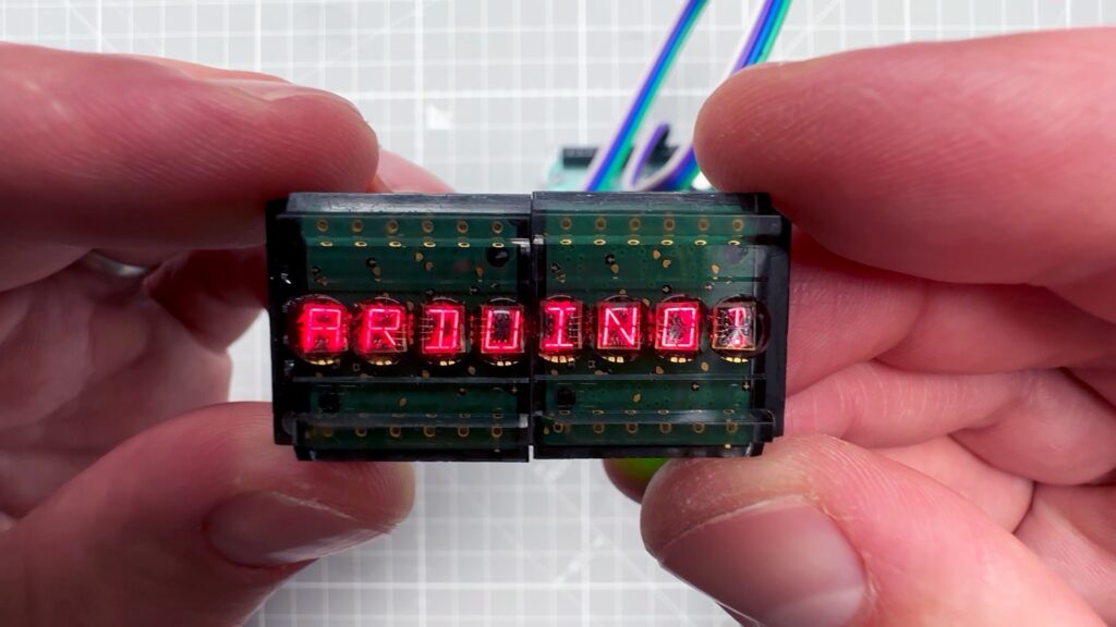
If you want to add a display to your Arduino project, the easiest solution will likely be an LCD or OLED screen. But though those are affordable and work really well, they may not provide the vibe you’re looking for. If you want a more vintage look, Vaclav Krejci has a great tutorial that will walk you through using old-school LED bubble displays with your Arduino.

Krejci’s video demonstrates how to use HPDL-1414 displays, which are what most people call “bubble” displays, because they have clear bubble-like lenses over each character’s array of LEDs. They were fairly popular in the late ‘70s and ‘80s on certain devices, like calculators. These specific bubble displays can show the full range of alphanumeric characters (uppercase only), plus a handful of punctuation marks and special symbols.

The HPDL-1414 displays Krejci used come on driver boards that set the characters based on serial input. In the video, Krejci first connects those directly to a PC via a serial-to-USB adapter board. That helps to illustrate the control method through manual byte transmission.
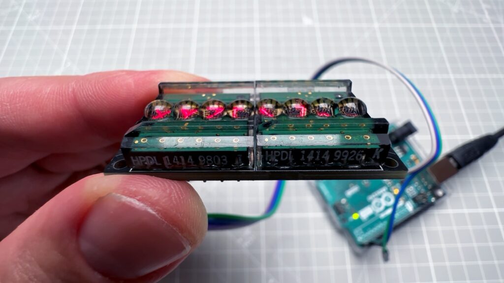
Then Krejci gets to the good stuff: connecting the HPDL-1414 bubble displays to an Arduino. He used an Arduino UNO Rev3, but the same setup should work with any Arduino board. As you may have guessed based on the PC demonstration, the Arduino controls the display via Serial.print() commands. The hex code for each character matches the standard ASCII table, which is pretty handy. That makes it possible to Serial.write() those hex codes and even Serial.write() the actual characters.

Don’t worry if that sounds a little intimidating, because Krejci has sample code that will let you easily turn any arbitrary array of characters into the serial output you need. Now you can use those awesome bubble displays in your own projects!

The post How to use vintage LED bubble displays with your Arduino appeared first on Arduino Blog.
DexteriSync lets you walk a mile in the gloves of a user with manual disability

Good designers prioritize the user experience — particularly the experience of users with disabilities that affect their perception and fine motor skills. A young person without disabilities, for example, may feel that jars are easy to open, while an elderly person with reduced hand strength may have the complete opposite experience. To help designers better understand the experience of people living with disabilities related to hand dexterity, a team of graduate students from Keio University and the University of Maryland developed DexteriSync.

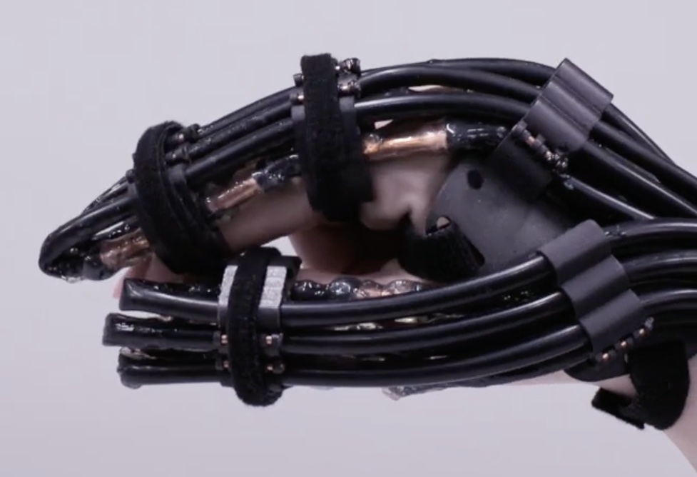
DexteriSync is an exoskeleton-like device worn on the hand. But unlike most exoskeletons, DexteriSync reduces the user’s ability instead of expanding it. It does so via thermal manipulation. If you’ve ever had numb hands following a snowball fight, you know how much the cold can affect your dexterity. In fact, skin temperature is one of the biggest factors related to hand and finger dexterity. By controlling the user’s skin temperature, DexteriSync is able to induce a reduction in dexterity and that could be useful to designers that want to make their products accessible to those living with disabilities.

DexteriSync is able to cool the wearer’s skin by pumping cold water through tubes attached to the 3D-printed exoskeleton frame. Copper contacts on the tubes help to make the thermal transfer more efficient. Peltier coolers remove heat from the pumped water, with an Arduino UNO Rev3 board controlling that process and monitoring the water temperature with a K-type thermocouple paired with a MAX6675 amplifier.

The team performed two user studies to evaluate DexteriSync. The first was intended to test the dexterity of users. The goal of the second was to determine if DexteriSync could affect user thermal perception. Both studies found that DexteriSync did have a noticeable effect.

The post DexteriSync lets you walk a mile in the gloves of a user with manual disability appeared first on Arduino Blog.

This disturbing Halloween doll was brought to life with Bottango

Halloween is popular for a lot of reasons and it is safe to say that “creative expression” is near the top of the list. That extends beyond store-bought costumes and decorations to DIY projects. If you want an excuse to make something impractical, Halloween can provide that. And if you want that thing to move, an Arduino and Bottango software are there to help, as proven by this disturbing animatronic Halloween doll built by Cameron Coward.

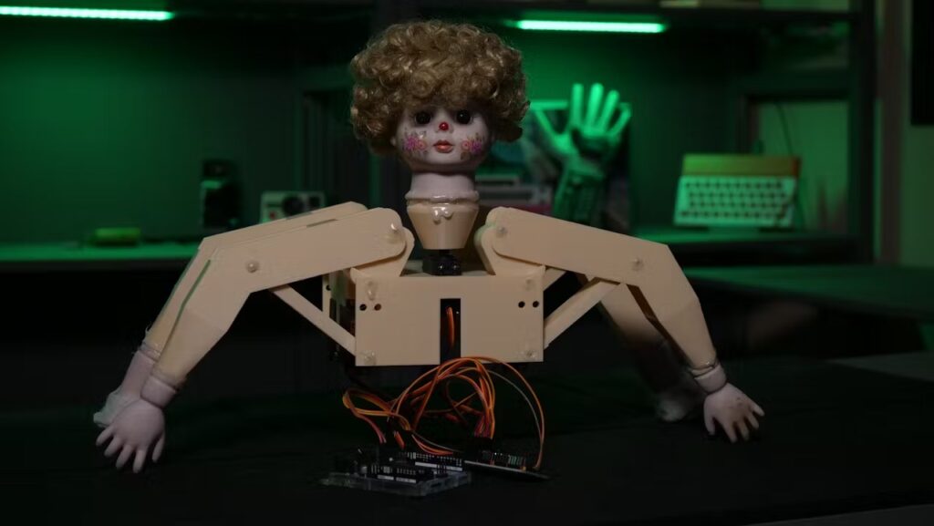
Coward started with a creepy doll procured at a thrift store, putting its porcelain head, hands, and feet onto a 3D-printed skeleton. The skeleton’s arms and legs are four-bar linkages, which produce the unnerving motion that falls into the uncanny valley. In total, there are five servo motors: one for rotating the head and four for actuating the limbs. 

An Arduino UNO Rev3 board controls the servo motors through an Adafruit 16-channel PWM servo driver board. That Arduino acts as a hardware driver for Bottango, which is software that was developed specifically for animatronics projects like this one. 

Using Bottango, Coward was able to create complex animations that involve all of the servo motors moving simultaneously. A child-size onesie (another thrift store find) covers the skeleton and electronics, completing the illusion of a doll come to life. 

The post This disturbing Halloween doll was brought to life with Bottango appeared first on Arduino Blog.

Using Arduino UNO to sync a visual neuroscience lab

Common research methods to study the visual system in the laboratory include recording and monitoring neural activity in the presence of sensory stimuli, to help scientists study how neurons encode and respond, for example, to specific visual inputs. 

One of the biggest technical problems in the neural recording setups used in such experiments, is achieving precise synchronization of multiple devices communicating with each other, including microscopes and screens displaying the stimuli, to accurately map neural responses to the visual events.

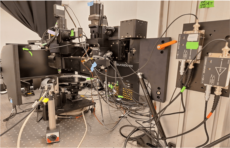
For example, in the Rompani Lab, a visual neuroscience laboratory at the European Molecular Biology Laboratory (EMBL) in Rome, the recording system (a two-photon microscope) needs to communicate with the visual stimulation system (composed of two screens) that are used to show visual stimuli while recording neural activity. To synchronize these systems efficiently, they turned to an Arduino UNO Rev3. “Its simplicity, reliability, and ease of integration made it an ideal tool for handling the timing and communication between different devices in the lab,” says Pietro Micheli, PhD student at EMBL Rome. 

How the setups works

The Arduino UNO Rev3 is used to signal to the microscope when the stimulus (which is basically just a short video) starts and when it ends. While the microscope is recording and acquiring frames, a simple firmware tells the UNO to listen to the data stream on a COM port of the computer used to control the visual stimulation. 

Within the Python® script used for controlling the screens, every time a new stimulus starts a command is written on the serial port. The microcontroller reads the command, which can be either ‘H’ or ‘L’, and sets the voltage of the output TTL at pin 9 to 5V or 0V, respectively. This TTL signal goes to the microscope controller, which generates time stamps for the microscope status. These timestamps contain the exact frame numbers of the microscope recording at which the stimulus started (rising edge of the TTL) and ended (falling edge of the TTL).

All this information is essential for the analysis of the recording, as it allows the researchers at EMBL Rome to align the neural responses recorded to the stimulation protocol presented. Once the neural activity is aligned, the downstream analysis can begin, focusing on understanding the deeper brain activity. 

Ever wonder what neurons that are firing look like? 

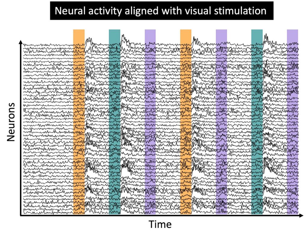
Micheli shared with us an example of the type of neural activity acquired during an experimental session with the setup described above. 

The small blinking dots are individual neurons recorded from the visual cortex of an awake, behaving mouse. The signal being monitored is the fluorescence of a particular protein produced by neurons, which indicates their activity level. After the light emitted by the neurons has been recorded and digitised, researchers extract fluorescence traces for each neuron. At this point, they can proceed with the analysis of the neural activity, to try to understand how the visual stimuli shown are actually encoded by the recorded neural population.

The post Using Arduino UNO to sync a visual neuroscience lab appeared first on Arduino Blog.
Use sound to trigger your camera’s flash with this DIY device

In the world of photography, the exposure triangle is immutable. To get a properly exposed photo (not too bright or too dark), you need a balance of aperture size (how much light gets in), shutter speed (how long the light gets in), and ISO (sensitivity to light at the expense of noise). But the shooting situation often limits how the photographer can adjust each parameter. To freeze action, for example, you need a very fast shutter — reducing the light you let in and therefore exposure. To compensate, you might need to use a flash and this DIY device can help with the timing.

There is a reason that photography flash units only come on for a split second (about 1/10,000th of second is normal): they’re incredibly bright and would burn out if left on for any length of time. To freeze action, such as a balloon popping, you need a fast shutter speed. Too slow and the photo will be all blurry. Exact numbers vary, but 1/8,000th of a second isn’t unusual for the mechanical shutter on a modern mirrorless camera. To get proper exposure, you need to time the shutter to open at the exact same time that the flash is illuminating your subject and that is something you could never achieve through manual control.

That’s hardly a new problem and so cameras are capable of releasing the shutter at the proper time in relation to the flash, but how do you sync those two events with whatever action you want to freeze? If that action happens to make a noise, this device is the solution.

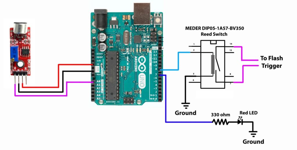
This device, based on an Arduino UNO Rev3 board, uses a microphone to listen for loud noises. If a noise exceeds a set threshold, the Arduino triggers the flash. An isolation circuit made with a Reed switch protects the Arduino from the high voltage of the flash. Reed switches are relatively slow, but they’re affordable. For better performance, an opto-isolator could be used instead.

To demonstrate this, students at Rochester Institute of Technology froze the action on some balloon pops and the results look great.

The post Use sound to trigger your camera’s flash with this DIY device appeared first on Arduino Blog.
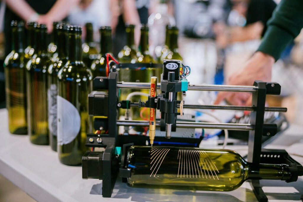
Transform trash into treasure with the DIY Bottle Plotter

Manufacturers put a lot of effort into their packaging (there is an entire engineering discipline just for that) and some of it can be quite beautiful. But it usually still ends up in the landfill or, at best, in a recycling center. However, if you’re the type of person who can see the beauty in wine bottles, mason jars, and tin cans, then you can build the Bottle Plotter to transform trash into treasure.

This machine, developed by VGaman, is a CNC pen plotter with one linear axis swapped out for a rotary axis. That means that instead of plotting on a traditional XY plane, it plots around a cylinder. The “pen” can be anything that fits in the holder and the possibilities are almost endless. Paint markers seem especially well-suited to this kind of work, but there are certainly other options that may produce interesting results on some materials.

The Bottle Plotter is relatively affordable to build, as most of the parts are 3D-printable. The exceptions are fasteners, bearings, rods, and the electronic components. Those electronics include an Arduino UNO Rev3 board, a CNC shield, and stepper motors. VGaman’s design does include a Z axis (to move the pen closer to and further from the workpiece surface), so the machine requires three stepper motors. 

The Arduino runs GRBL firmware and can accept any compatible G-code. The easiest way to generate that G-code is with a plugin for Inkscape, which will let users create artwork and then plot that all within one piece of software. Swap pens between toolpaths to make cool multicolor designs!

The post Transform trash into treasure with the DIY Bottle Plotter appeared first on Arduino Blog.

Giving Billy Bass the arti-fish-al intelligence he always deserved

If you were unlucky enough to visit a big box retail store or goofy uncle’s home around the turn of the century, you would have undoubtedly come across a Big Mouth Billy Bass. That’s an animatronic fish that wiggles on a plaque while older, very licensable hit songs play. But while ol’ Billy was wildly popular at the time and spawned a whole new market segment, he wasn’t very sophisticated. Tony–K decided to address those cognitive shortcomings by giving Billy Bass an ‘arti-fish-al intelligence’ upgrade.

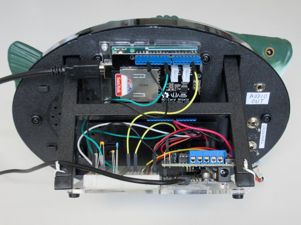
Internally, the original Big Mouth Billy Bass is quite simple. It has a single electric motor that drives the animatronic movement through a plastic mechanism, with a cheap sound chip that has Al Green’s “Take Me to the River” burned in. Tony–K’s modification gives the user full control over everything, so they can program whatever behavior they like and use any audio. Using a standard infrared remote control, the user can activate those programmed sequences. If desired, Billy can be switched back to his normal routines.

Tony–K achieved that using two Arduino UNO Rev3 boards. One handles motor control, while the other plays audio. Tony–K chose to do that so he could use a motor driver shield with one Arduino and an SD card shield with the other. This takes advantage of the TMRpcm library, which makes it possible to play PCM and WAV files without a dedicated audio DAC (digital-to-analog converter). The audio quality won’t be stellar, but it is good enough for this purpose.

What to play all comes down to the builder’s ability to think up fish-related puns. If you can find a way to incorporate a Jimmy Buffett song, you’ll be golden!

The post Giving Billy Bass the arti-fish-al intelligence he always deserved appeared first on Arduino Blog.

❌